If you think about it, an FM
exciter is a transmitter.
All it needs is a power
amplifier to get RF to a
desired level. That makes
the exciter a vital link in
the broadcast chain. An
exciter is a bit complex in
how an RF carrier is created
and how audio impressed on
it, but it's not rocket
science.
I see exciters in the
shop that suffer various
ills, almost all of them
taking a station off the
air. Here's a grab bag of mods and repairs that may
help you in future.
|
|
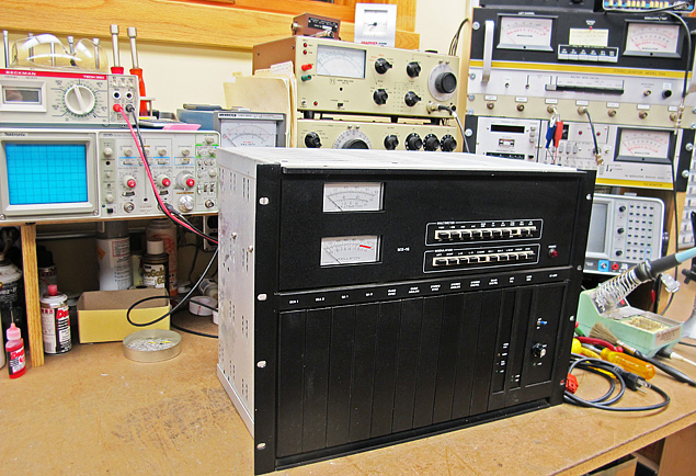
A Harris
MX-15
exciter is
shown on the
testing
bench.
|
|
One of the modifications I
like to make to exciters is
to add a power control on
the front panel. I've had
enough of poking a jeweler�s
screwdriver through a hole
in the top of an exciter to
make an adjustment. Many
transmitter tune-ups involve
tweaking exciter power to
get things just right. A
control with a knob makes
that job so much easier.
I also like to add a
screwdriver-adjustable
composite input level
control on the rear so
modulation can be adjusted
easily.
The Harris THE-1 FM exciter
has an output RF amplifier
that can fail. Repairing it
could be an expensive job,
because the original
manufacturer of the RF
transistors is out of
business. There appears to
be no substitute for them.
Harris has just a few
complete working amplifier
modules on hand at $2,128
each. Ouch! The exciter
isn�t worth that when
operational. I was faced
with this dilemma recently
and discovered an answer. It
is the FM70 pallet amplifier
for about $150 from
Broadcast Concepts in
Miami.
|
|
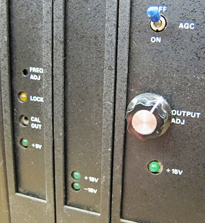
Power
control
knob
as
added
to
MX-15
exciter
|
|
|
|
|
(click
thumbnail)
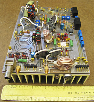
Original
PA
module
in
THE-1
exciter
|
|
|
By cutting away part of the
existing amplifier circuit
card carefully and bolting
this replacement amplifier
in place, I was able to
revive two THE-1 exciters.
Wiring has to be reworked
too. The existing RF output
low-pass filter was probably
responsible for the
transistor failure in the
first place. With an exciter
terminated into a dummy
load, a return loss
measurement at the input to
the filter showed about 8
dB, when it should have been
at least 20 dB. Retuning the
filter was the fix.
|
|
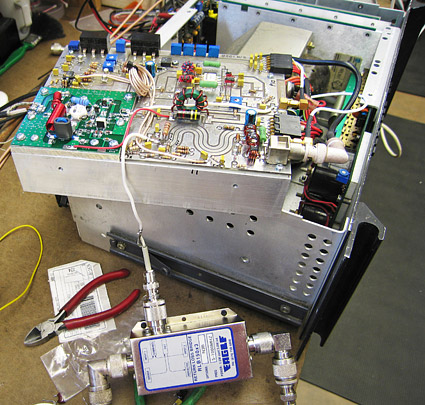
Revised
THE-1 module
being tested
with return
loss bridge
|
|
In the end, the exciter did
not put out its rated 55
watts but topped out at 30
to 40 watts depending on
which end of the FM band it
was on. There wasn't enough
gain in the design to get
full power. Most stations
don�t need that kind of
power anyway. Ten watts is
pretty standard especially
for tube transmitters.
Protection
Speaking of tubes, any
solid-state exciter that
feeds the tube input stage
on a transmitter needs to be
protected by a shorted
quarter-wave stub. An
arc-over in that tube could
put 1,000 volts on the
output transistor of an
exciter, causing an
immediate failure.
Continental Electronics has
recommended these devices
highly for years.
You can build one by
shorting a piece of coaxial
cable at one-quarter
wavelength from a "T"
adapter on the output of the
exciter or input to the
transmitter. The difficult
part is getting the length
right so the exciter sees no VSWR when the stub is in the
circuit. I do that in the
shop by using a spectrum
analyzer with tracking
generator and a return loss
bridge. It�s amazing how the
right test equipment makes
almost any job easy.
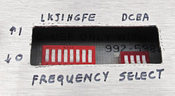
|
|
DIP
switches
accessed
through new
hole in
cover
|
|
Many exciters are kept in
standby status so they can
be put on any frequency at a
moment�s notice to
substitute for a failed
exciter. Almost every
exciter that comes into the
shop here gets a new set of
DIP switches for frequency
selection. That means
putting switches in place of
wire jumpers or replacing
existing switches, which may
fail after 20 years of
service.
In the case of a Harris
MS-15 or MX-15, I cut a
rectangular hole in the AFC
module cover so the switch
positions can be changed
easily without taking the
cover off. Caution: Anyone
setting up an exciter with
switches needs to put it
into a dummy load and
frequency counter on a
sample port before
attempting to put it in
service. There is always a
chance that the switches may
be set incorrectly and the
exciter is playing merrily
on the wrong frequency. I�ve
seen that before, and the
transmitter doesn�t tune
with beans.
Many exciters show up in the
shop here with the complaint
that the station is being
heard on three or more spots
on the FM dial. Management
likes the idea, the FCC
doesn�t.
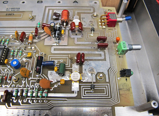
|
|
MX-15 PA
module with
replacement
capacitors
|
|
The problem usually is a
dried-out electrolytic
bypass capacitor or two in
the RF power amplifier stage
of the exciter although I
have seen it happen in the
modulated oscillator section
and power supply. Basically
any oscillation, typically
in the 100 kHz to 1.5 MHz
range, will modulate the
exciter's signal to appear
above and below the assigned
frequency by that amount.
Keeping the spectrum clean
is an ongoing job for
broadcast engineers.
|