|
It is easy to
do the minimum on a job. You�ve
seen it happen, and so have I.
Sloppy work degrades an
installation and can be an
eyesore. Ultimately, it can
become a �house of cards� that
collapses upon itself. Why
should anyone settle for that?
I make a conscious effort to do
clean work, even if previous
work was done poorly in that
location. In essence, I kicked
it up a notch. You should, too.
It�s better to take a little
extra time to do it right the
first time than have to face the
consequences of a bad
installation later.
TAKE PRIDE IN YOUR WORK
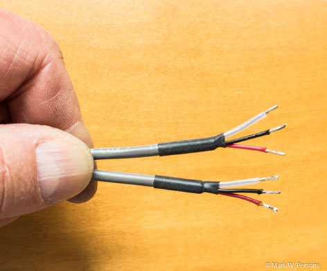 |
Fig. 1 illustrates a
method of doing clean
installations. Two
shielded pair audio
cables are prepared for
termination. The
otherwise bare shield
drain wire is covered by
clear heat shrink
tubing. Likewise, the
foil shield end of the
cable is protected from
touching something it
shouldn�t by black heat
shrink tubing. It takes
less than a minute to do
the job and is worth it
because it prevents
problems. |
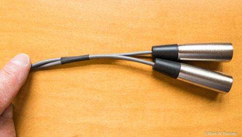 |
Fig. 2 shows two
shielded pair cables
that have been twisted
together to form a
stereo pair. Yes, I know
there are stereo cables
that come from factories
bonded together. The
point here is that heat
shrink tubing is used to
keep the cables from
being separated from
each other. This kind of
organization is the
right thing to do to
avoid confusion later. |
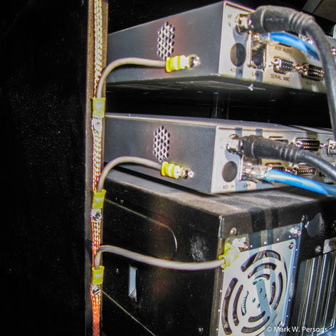 |
Fig. 3: Good grounding
in a wooden rack. |
RACK GROUNDING
Sometimes broadcast
equipment winds up in a wooden
rack. In that case, the
equipment needs to be grounded
more than ever.
Fig. 3 Shows such an
arrangement, in which copper
braid is run vertically on a
cabinet member, then short
jumpers are screwed to the braid
and to each piece of equipment.
The braid was the shield, pulled
from a piece of RG-8 cable. The
jumpers are two-pair audio
shielded cable with all
conductors bared and crimped
into a terminal at each end.
These are larger than normal
size wire terminals because they
have to handle five wires at a
time. The jumpers are short with
rounded corners, not square, to
make it easy for lightning to
follow to ground. The best
practice is for jumpers to have
an insulating jacket so they
don�t cause a problem when
accidentally touched to
something else in the rack.
On that same point, bonding
wires between equipment and a
rack are still proper even when
the rack is metal. Paint on the
rack can, in some cases,
insulate the rack from
equipment. The best choice is to
run a one inch or larger copper
strap on the inside of a rack,
top to bottom, bolted to one
side. Make sure that strap goes
to station ground � you�ll be
very embarrassed if there is
lightning damage, if you haven�t
connected it.
[More Tech Tips: "Yes You Can
Build Your Own"]
 |
|
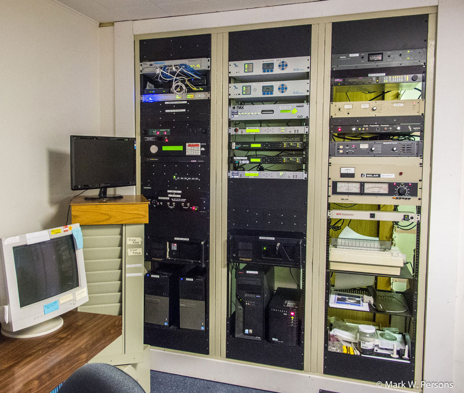
Fig. 4: A custom wood
equipment rack. |
Fig. 4 shows a three-bay
equipment rack system that was
constructed on site with a
minimum of expense. The area
started out as a closet, which
was accessed from the other
side. The wall was partially
dismantled and reconfigured with
metal rack rails.
Middle-Atlantic Products makes
model RRF-45, 78-3/4 inches,
just for this purpose.
Smaller rails are available too.
The rails are L shaped to screw
to the wood sides. They have a
series of drilled and tapped
10-32 holes where 19-inch
equipment can be bolted in.
(Measure twice and cut once when
doing this.)
The station had a carpenter
install three 2x6 studs, side by
side, at each dividing point
between rack bays. The carpenter
left an additional 3/16 inch
between the sides to make up for
errors. Rack rails were then
screwed to the wood with small
flat washers to get the spacing
exactly right. Fig. 5 shows the
closet door open so the
equipment can be worked on from
the back side.
There are plastic cable clamps
used for routing cables and
outlet strips to plug the
equipment into between the rack
bays. Yes, there are grounding
conductors running behind the
wiring too. The photo was taken
after a few years of use, so the
wiring is not as neat as I would
normally like to see.
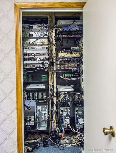 |
Fig. 5: The back of the
rack seen in Fig. 4 |
STL PROBLEM
This is an interesting
and true tale of hum and buzz in
a 950 MHz STL system. At
first, it was assumed that there
were bad electrolytic capacitors
in the STL transmitter or
receiver. Replacing the pair
resulted in the same problem.
Further examination revealed
that an external 950 MHz RF
preamplifier, at the receive end
of the system, was the cause.
How could that be?
 |
 |
|
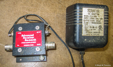
Fig. 6: An STL
preamplifier with a
problem. |
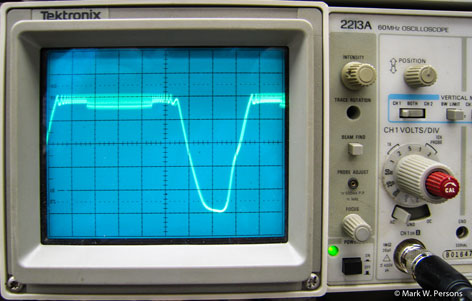
Fig. 7: An oscilloscope
reveals the answer. |
Fig. 6 shows the preamp was
powered by a 12 VDC wall-wart
that has an electrolytic
capacitor inside to smooth out
DC. The capacitor failed by
opening up, resulting in DC with
a high component of AC ripple
feeding the preamplifier. Fig. 7
shows what the supply voltage
looked like on an oscilloscope.
Ouch! The preamplifier, in
essence, turned on and off at a
120 Hz rate, thus the buzz in an
already weak FM STL signal.
SITE CLEANING
You�ve seen it before, a
transmitter site that is
overgrown by brush. There is at
least one good tower contractor
in Minnesota who brings a �brush
hog� to sites when doing
inspections. The operator clears
a path from the tower to each
guy point and then around each
point to facilitate maintenance.
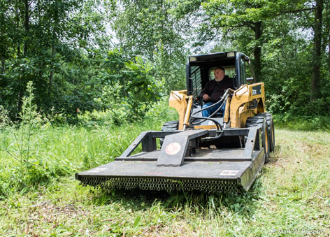 |
Fig. 8 shows a brush hog
clearing around the
transmitter building
too. Nicely done. Hogs
have large tires that
are unlikely to damage
an AM ground system.
Best to stay away from
in front of a machine as
it might throw a rock in
your direction. |
AM ground system damage can be
repaired easily � if discovered
when it happens.
The normal specification for an
AM ground system is 120 #10 bare
copper radials going out for
about 1/4 wavelength like
equally spaced spokes of a
wheel. The usual practice is to
bury them 4 to 6 inches below
the ground surface.
When a copper ground wire is
cut, just grab the ends and pull
them up so 6 inches or more is
showing. Mark them and come back
with a 12-inch or longer piece
of #10 bare copper wire. Twist
the ends together and then braze
with an oxygen and acetylene
torch. You can use a Mapp gas
torch, but they don�t get as
hot.
For brazing rods, I use Sta-Silv
15, which contains 15 percent
silver. You don�t use a lot, so
the cost is not that steep. Do not use
ordinary tin/lead solder. It
will deteriorate underground and
fail.
 |
|
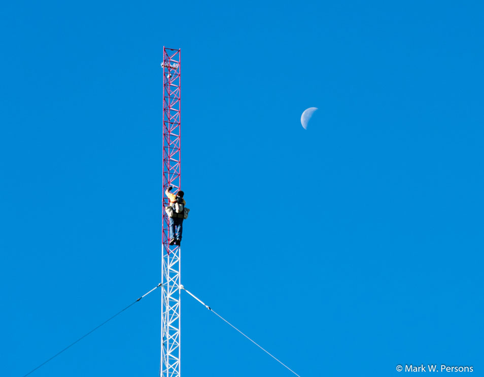
Fig. 9: A tower worker
climbing almost to the
moon in the early
morning. |
If you work indoors, you miss
some of the great scenery that
engineers often witness.
Use your head to do the job
right the first time. It makes
perfect sense.
Comment on this or any article.
Write to radioworld@nbmedia.com. |