|
Give your AM listeners a pleasant experience with natural-sounding
audio.
First I’ll tell what you already know. Back in the day, AM broadcasting
was king and FM was commercial-free. Things changed in the 1970s as FM
grew in popularity. Here we are 40+ years later with many AMs
struggling. Some have gone away because they were no longer financially
viable. To make matters worse, AM directional stations are more
time-intensive and costly to maintain, especially when compared to FM
stations.
On the positive side, I know a number of smaller AM/FM combination and
standalone AM stations in Minnesota that are doing well. One town has a
1 kW AM with a 100 kW FM. The AM brings in 40% of the sales revenue
because it has always been locally programmed with live announcers until
1 p.m., then is live again during afternoon drive.
AM radio isn’t supposed to sound bad. It can be a clean and pleasurable
listening experience, even when there is only 3 kHz of audio bandwidth.
On the other hand, AM can be ugly to the ear when there are
maladjustments.
SCIENCE
Modulation is the process of adding audio to a transmitted
signal. Amplitude modulation is aptly named. A station’s carrier
(transmitter power) is varied by the station’s audio. Carrier power is
depressed to zero watts to achieve 100% negative modulation. It
increases to 1.5 times carrier power when 100% positive modulation is
reached. That is why a thermocouple antenna ammeter reading rises with
modulation. You read it during a programming pause to get an accurate
measurement.
METERING
AM modulation monitors have –100% and +125% lights indicating
overmodulation. You really don’t want those lights to come on. More is
not better. First, be sure to set the monitor’s RF carrier level
control so the carrier meter needle is in the right spot, as per
manufacturer’s instructions. A carrier meter misadjustment will result
in inaccurate modulation monitor readings.
Fig. 1 shows an AM modulation monitor. The –100% and +125% lights are on
and yet the analog modulation meter reads only 94%. It is normal for an
analog meter to read lower than actual modulation. In fact, 85 to 90% is
a more realistic meter display, because it cannot track peaks as lights
do.
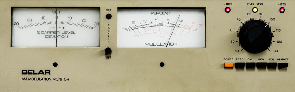 |
Fig. 1: AM modulation monitor showing overmodulation.
|
|
A monitor’s audio output will sound excessively bright or harsh
if a de-emphasis audio circuit is not included. Monitors
traditionally do not have this, but often a simple capacitor and
resistor modification will do the trick. The idea is to undo the
high-frequency boost that is a part of the audio processing, per
the National Radio Systems Committee (NRSC) standard. As you
probably know, the transmitted audio has increased
high-frequency response to overcome high-frequency rolloff in
most receivers. The goal is to restore flat frequency response
to the listener. Some audio processor manufacturers are using
non-standard pre-emphasis curves to suit their taste. That
complicates getting a realistic feel for frequency response. At
least they are trying to make the best of receiver frequency
response roll-off.
ON A
SCOPE
An article I wrote regarding the operation of
oscilloscopes, “Your Scope Is a Tool for all Seasons,” appeared
in the Jan. 13, 2013, edition of Radio World. To refresh
your memory, a scope has a display where a dot that travels from
left to right is deflected up and down with voltage. In this
case, we will look at a transmitter’s RF output. |
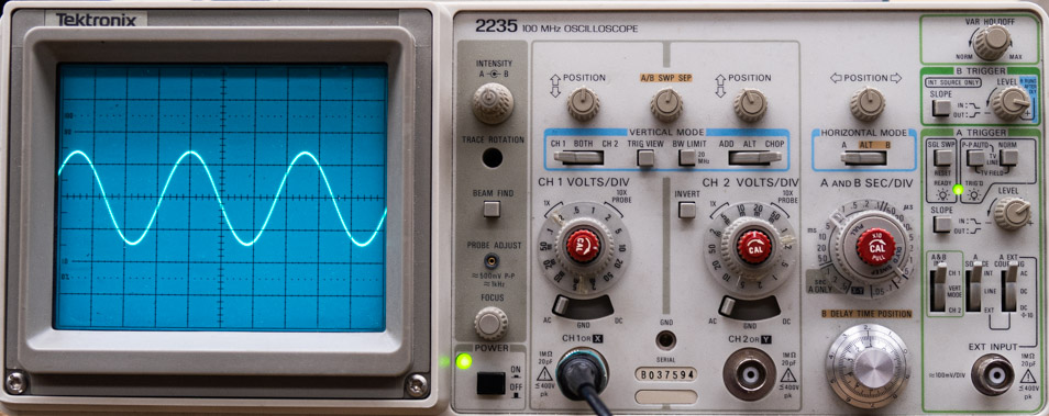 |
Fig. 2: An AM RF carrier wave on an oscilloscope.
|
I’ll begin with Fig. 2. It shows an oscilloscope with a view of
the transmitter’s carrier with the scope sweeping at high speed
(0.2 microsends per horizontal screen division) to see the
actual carrier wave of an AM radio station. By carrier, I mean
the transmitter’s power output. What you see is an almost
perfect sine wave at the station’s operating frequency.
|
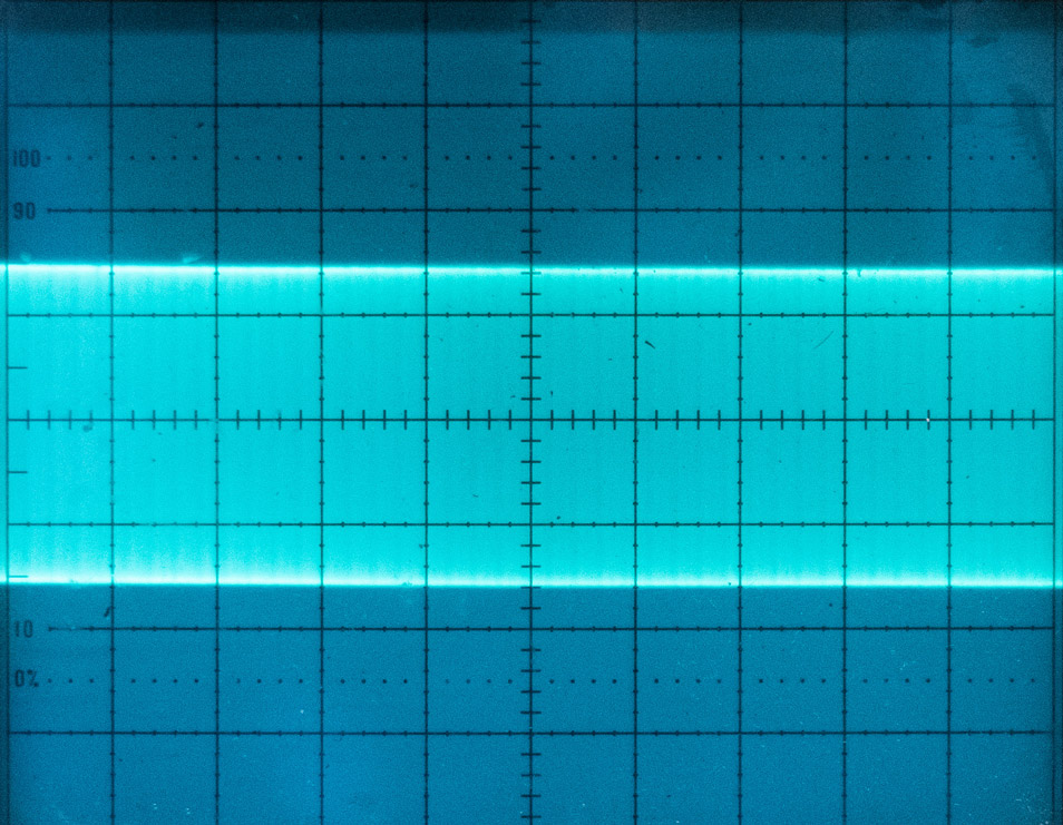 |
Fig. 3: A carrier with no modulation.
|
Let’s zoom in to the scope’s screen. Fig. 3 shows the carrier
when the oscilloscope is slowed down to view audio (0.2
milliseconds per division). No modulation was present at that
instant. Fig. 4 shows a 1 kHz sine wave modulating the carrier
100% positive and negative. The positive parts are the top and
bottom peaks. They are mirror images of each other. The negative
modulation part is where the carrier is just pinched-off at zero
power in the center of the screen. This sine wave is relatively
clean/undistorted, with less than 0.5% audio harmonic
distortion.
|
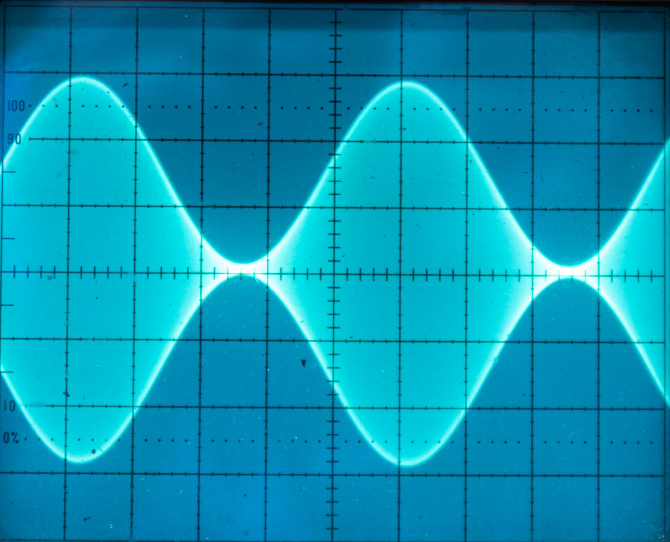 |
Fig. 4: A carrier modulated 100% with a 1 kHz sine wave.
|
Many receivers do not reproduce it that way. The last 5 or 10%
of negative modulation, between 90 and 100%, is where receiver
detectors have trouble faithfully reproducing what the
transmitter is sending. The result is audio distortion. We all
know that unwanted audio artifacts are a listener turnoff.
|
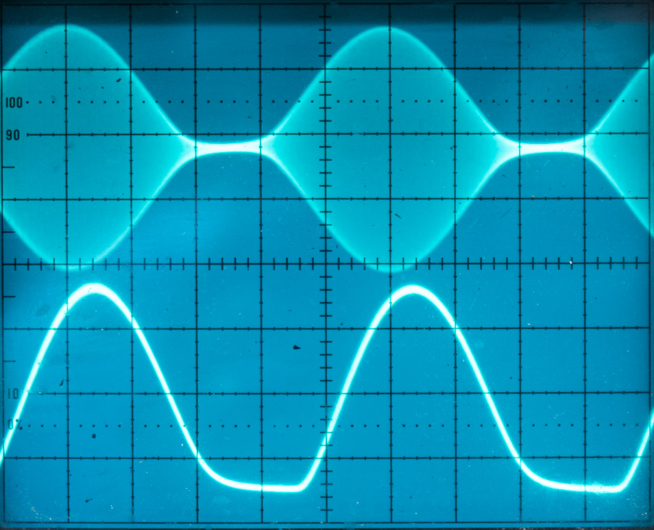 |
Fig. 5: 100% modulation with receiver detector output.
|
In Fig. 5, I’ve switched the oscilloscope to dual trace mode. It
shows the transmitter at 100% modulation on the top trace. The
bottom trace was sampled at the receiver’s detector. I made the
measurement there so it rules out additional audio harmonic
distortion, which might be added in the output stage. By
definition, harmonic distortion is where this 1 kHz audio tone
will have unwanted audio products at 2 kHz, 3 kHz, 4 kHz etc.
because of non-linear system performance. In this case,
distortion from transmitter through the receiver detector
measured 5.1%. It was only 3.1% at 90% modulation.
|
|
|
Fig. 6: 125% positive modulation, 100% negative modulation with
receiver detector.
|
|
Fig. 6: Traditional analog audio processing used diodes to clip
the negative side of audio before it went to the transmitter so
it would not attempt to overmodulate the negative modulation
while allowing positive modulation to go to 125%. The downside
is that it added as much as 6.5% harmonic distortion in the
process. Add the receiver’s problems to the mix and you have a
whopping 10.2% distortion. Ouch! You’d never allow that on FM.
Newer digital processors reduce but may not eliminate the
problem. Yes, the station can be a bit (about 0.9 dB) louder on
the dial, but it is irritating to many listeners. They don’t
know how to describe it, but oops,
there goes another tune-out! Again, some people hear it and some
don’t. Best not to penalize the station with high modulation. |
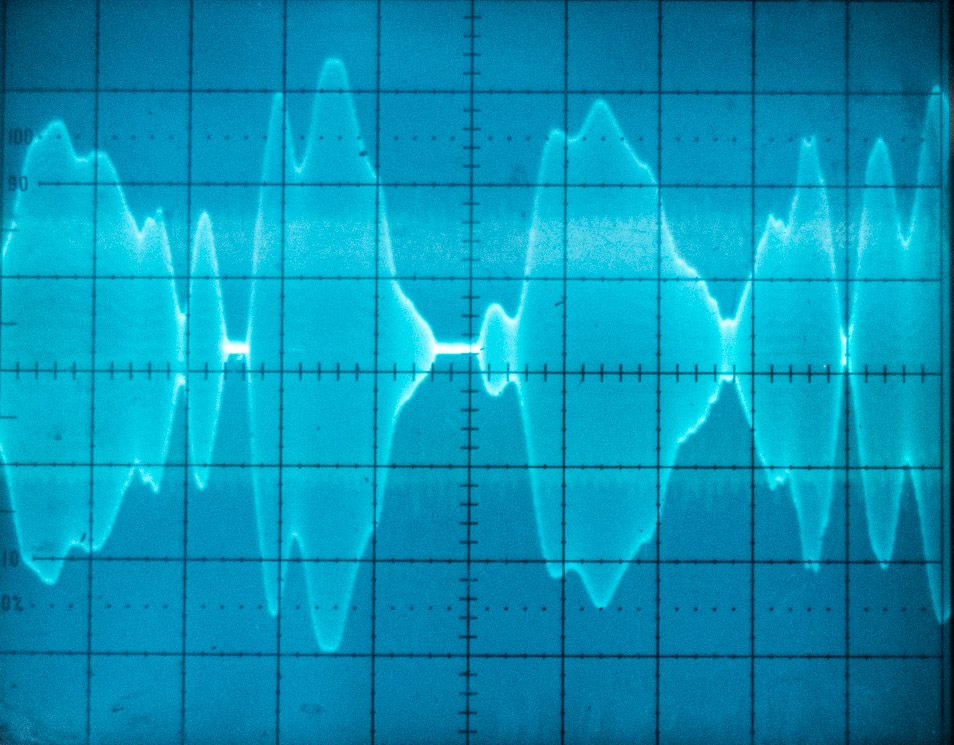 |
Fig. 7: The transmitter is being badly over-driven at 100%
negative modulation.
|
|
Fig. 7 shows the transmitter being modulated at over 100%
negative modulation. I’ve moved the scope’s trace up a bit so
you can see detail. Negative peaks go flat to the center, which
is no carrier at that instant. Modulation like this will not
pass the required NRSC occupied bandwidth nor will it pass my
ear test for listenability. It is tiring to hear.
Fig. 8 is where you want to be. No more than 95% negative
modulation, the sweet spot between loudness and listenability. |
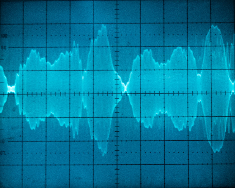 |
Fig. 8: 95% program modulation of the carrier.
|
|
It is a shame to lose listeners for that last 5% (about 0.5 dB)
of modulation. Few if any will hear the loudness difference.
Likely most will hear grit in the audio of transmitters
modulated to the max. You can make up much of the modulation
percentage difference with careful adjustments of the audio
processing, before it
goes to the transmitter. Software-defined receivers eventually
will solve much of this problem, but we need to deal with
today’s radios.
When I was installing AM stereo years ago, negative modulation
was usually set at 95% and positive modulation at 95% for
stations to sound clean. It was positive +125% if the client
preferred it. That extra positive modulation comes as “forced
asymmetry” where the negative audio peaks are soft clipped so
the positive peaks can go higher. Ouch!
Surprisingly, bad-sounding audio with less than 100% modulation
will usually fit into the NRSC occupied bandwidth mask, in the
FCC required annual measurement. That is because of the required
9.5 kHz low-pass filter in audio processing.
AM stations competed in loudness wars to beat the other guy
years ago. Now it is time to give listeners a pleasant
experience with natural-sounding audio. Don’t drive them away.
I grew up in a broadcasting family that owned two AM stations
and no FM. Success was dependent on keeping listeners. Loudness
was not the answer. |
|
Mark Persons, ham W0MH, is an SBE Certified Professional Broadcast
Engineer and SBE Engineer of the Year in 2018. He is now retired after
more than 40 years in business. His website is www.mwpersons.com.
Email
December 4, 2019: I
found Mr. Persons' article very informative and helpful. Distortion is a
turn-off.... and I had never considered the distortion inherent in the
garden-variety AM envelope detector in the home receiver.... shame on me.
Hopefully, this will lead to better sounding AM. One nit to pick: The
peak power for a 100% modulated AM signal is four times carrier power, not
1.5 times as stated in the article.
James Thoruson, Central
Coast Electronics.
Answer:
Average power is what I was thinking of when writing the article. Mr.
Thoruson is correct in saying that peak power is four times
unmodulated power. Mark
Persons
Email
December 4, 2019: Mark:
Thanks for pointing out that modulation percentages above 95% are recovered
with higher distortion in AM receivers and add little to the coveted, by
most engineers, loudness. I always operated the AM stations that I was
associated with at no more than 95% negative modulation. Glynn
Walden
Email:
November 6, 2019:
Hi Mark, I enjoyed your modulation article in Radio World. It
should be required reading for a lot of the "Wanna be" radio station
engineers today.
Bill Riches, dB Electronics, Cape May, NJ.
Email
October 27, 2019:
Great article in the October 9 Radio World, "Finding Your Modulation Sweet
Spot." As a former engineer, now a radio station owner, (I liked engineering
better), AM or FM, I don’t care as long as I have a great sales staff and
fantastic local programming. I recently purchased an AM in Orlando on 660 and
we started a fun, new local talk station that is really starting to take off.
Thanks for the great insight and very useful information on your
website. John Caracciolo, President and CEO of JVC Broadcasting. |
|
|
|