|
DAs are marvels of engineering but can seem daunting. Here are useful
tips!
Our previous
article
Find Your
Modulation Sweet Spot,
published in the Oct. 9, 2019, issue of Radio World, sets the stage for
a two-part discussion of AM directionals, beginning here.
As you surely
know, fewer engineers are qualified to work on AM directional antenna
systems today. Younger ones who maintain these marvels of engineering
may not be as well versed as their predecessors. If you are a
member of the new breed, my advice is to be careful not to do the wrong
thing when tackling a problem. Don't make adjustments without analyzing
a situation first.
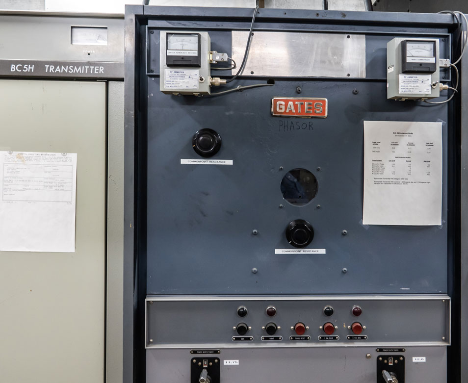 |
Fig. 1: A 1960s phasor with commonpoint controls added.
|
PROBLEMS
If you find antenna monitor phase and ratio readings are off
more than a few degrees or a tower radio is off more than 5%,
then do not start adjusting the phasor to compensate. Keep your
cool. Write down all the phasor dial readings for future
reference. Do a complete physical inspection, including
eyeballing the inside of the phasor cabinet and antenna coupling
networks. Look for broken connections everywhere and on lines
running to the towers. Go out and measure the monitor points.
You may find they are in spec and that your real problem is in
the antenna monitor or other part of the sample system. Jumping
to the wrong conclusion could result in chasing your tail to fix
an antenna problem that you don't have.
TOO MANY KNOBS
An engineer maintaining a two-tower AM directional antenna
station called me for advice recently. He is one of the
engineers I am mentoring. A station's commonpoint impedance (RF
input to the phasor) was difficult to adjust because the
variable commonpoint resistance coil was at one end of its
travel. All had been well a few months before. Today,
solid-state transmitters want to see exactly 50 ohms with near
zero reactance, as you know, so setting the commonpoint
impedance correctly is very important.
As it
turns out, the phasor has phase and ratio controls for both
towers. In this case, it was too many knobs. The ratio
controls could be tweaked on either tower to keep the station in
specs. This led to the commonpoint problem when he used both to
get the correct antenna monitor phase and ratio numbers. The
phasor input matching network was looking at a phasor buss
impedance that was not according to the original plan.
PHASOR
DESIGNS
It's
important to understand how phasing systems are designed and
built. A transmitter feeds RF power into a phasor cabinet, where
there is a three-coil impedance matching network. It feeds
RF energy to a point called the buss. This is where power is
rationed out to phase and ratio controls for each tower. The
buss is rarely 50 ohms, and it is normal to have the impedance
change a bit as an engineer tweaks phase and ratio controls to
maintain FCC licensed specifications. The input matching network
normally has enough operating range to compensate for these
adjustments.
Not all
phasors have a front panel adjusted ratio control for the
reference tower. That is for good reason. The reference tower
normally gets more power than the other tower or towers. There
is normally no need to adjust power to the reference tower after
the station is initially tuned and licensed. It is the
standard/reference that the other towers or towers are
compared/referenced to.
I told
the engineer to carefully adjust the reference tower ratio
control to full, or close to full on, while keeping the other
tower ratio and phase correct. Then, don't touch the reference
tower radio control again. Mark it as don't adjust. That
solved his commonpoint problem. He then had good resistance and
reactance control because the buss impedance was as expected in
the design. Also, running both ratio controls down to their
lower ends could cause some phasor components to run hot.
|
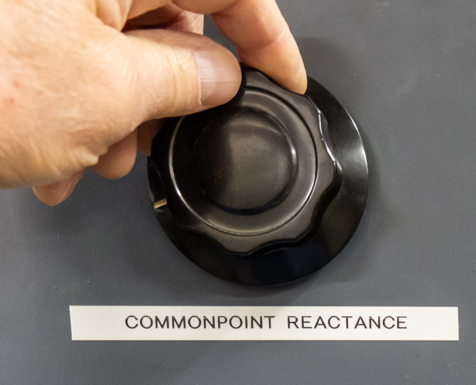 |
Fig. 4: Mark your normal dial settings for easy reference.
|
|
DESIGN
EVOLUTION
Phasor
systems did not typically have front-panel adjustable input
matching networks years ago when tube transmitters were the
norm. That changed when solid-state transmitters came along. Now
input resistance and reactance controls are required to keep
reflected power low and transmitters happy.
Fig. 1
shows a 1967 vintage Gates three-tower phasor. It did not
originally have an input matching network that is adjustable
from the front panel. I added those knobs to help control the
input impedance and transmitter power when switching from 5 kW
non-directional day to 5.4 kW directional night. One control is
for resistance, which is tweaked to keep the input at the
licensed 50 ohms. The other is commonpoint reactance. Fig. 2 is
the dial I normally adjusted to get the transmitter to make just
the right amount of power at night.
In this
case, the day non-directional antenna coupling unit has clips on
fixed coils for adjustments. Once set, it was good to go. The
maintenance procedure is to get the transmitter running at the
correct power level in the day mode, then switch to night and
adjust the night commonpoint reactance control to get the
correct directional antenna power. It is that simple.
You'll
also note there are FCC-required operating parameters listed on
the front of the phasor and transmitter. They are right where
needed most.
Yes,
that is a Gates BC-5H Transmitter next to the phasor. It has
been in full service, running 5,000 watts day and 5,400 watts
night since 1973. That's 46 years! This transmitter is on its
third high-voltage transformer, third set of AC contactors,
fifth set of high-voltage rectifiers and the solid-state audio
driver section has been rebuilt four times on site without
sending it to a factory for repair. The transmitter lives on,
but will likely be replaced by my engineering successor when the
next serious failure occurs. Fortunately there is a Collins 5 kW
AM to back it up. Both are excellent tube designs.
ANTENNA
EFFICIENCY
Can you
assume that all is well when the monitor points are below FCC
limits? Not necessarily. You might have serious impedance
mismatches and power divider mismatches, as described above. RF
power could be turning to heat.
You can
get a readout on antenna efficiency by going to the original
proof of performance documentation and making six or more
measurements in the major lobe or lobes. The readings should
agree, although there are seasonal variations. RF travels better
over frozen ground so winter signals are inherently a bit
higher. It is not a big deal in the first couple miles from the
transmitter. Ground loss changes become more apparent the
further out you go, especially at 20 miles and beyond.
OOS, OOM
Just
because the phasor doesn't have active components, that doesn"t
mean it should be ignored. Rodents get in sometimes and need to
be dealt with. Loose hardware is common on RF contactors because
they are usually operated twice a day with plenty of vibration
in the process. RF contacts wear and should be replaced before
they fail completely.
HEAT
Get one of those infrared temperature
meters and go through the phasor, then antenna coupling networks
looking for hot spots. Use it around electrical load centers
too. You might be amazed to find hot electrical contracts and
wires that are about to fail. Best to take care of the problem
before it causes an off-air emergency at a bad time.
|
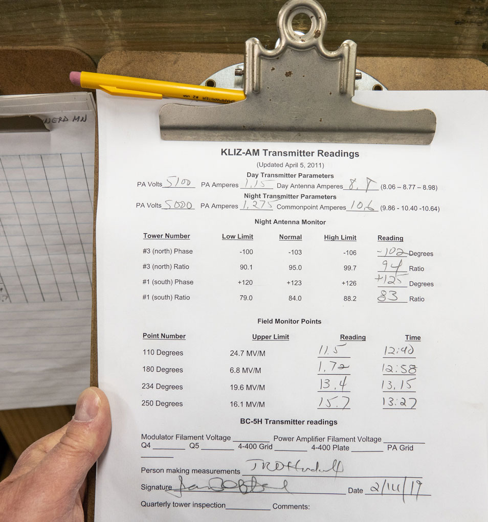 |
Fig. 3: Keep good records.
|
PAPERWORK
Keep Good visit-to-visit documentation on an AM directional
(Fig. 3). It is a history of how the system has been behaving.
You don't just log that everything is OK. AM directionals have
many parameters to keep track of. That includes phase and ratio
readings on each non-reference tower, dial settings on the
phasor, transmitter PA readings, commonpoint current and monitor
point readings. along with date and time. You'll likely see
seasonal changes on monitor point measurements.
|
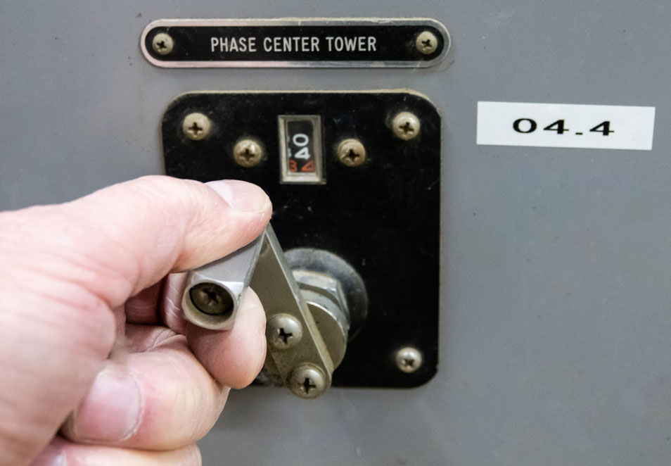 |
Fig. 4: A carrier modulated 100% with a 1 kHz sine wave.
|
|
Fig. 4
shows a phasor adjustment crank. Note that normal counter dial
reading is labeled nearby for easy reference. This is one more
way to prevent an "oops" from becoming a major problem.
You
should keep accurate phasor schematic documentation on hand at
the transmitter site. Designs and "as built" are often a bit
different. I recommend you pencil any changes on the original
schematic. Also, mark down the number of active turns on each
coil in the system. As you know, silver-plated straps with clips
are used to short out unused turns on fixed coils. They are set
once and then normally not touched again. It won’t take but an
hour to do the documentation and will save a lot of headaches in
the future. Lightning can blow up a coil or capacitor beyond
recognition. Having parts values and settings on a schematic
diagram can be a life saver.
A nearby
station was visited by vandals one night. Somehow they got into
the antenna coupling networks and pulled clips off the fixed
coils. No other damage, just mischief. It took the engineer only
an hour to put the coil clips back in the right spots, plus do a
little tweaking, to get the antenna system working properly
again. Imagine trying to start from scratch to get the system
operational without that knowledge. Ouch!
By the
way, spare parts and equipment manuals belong where the
equipment is, not back at the studio. That includes books and
programming information for remote control systems.
The best
is yet to come. Stay tuned for an upcoming issue, where you'll
find a real-life story about a 197-foot tower that came down in
the parking lot at a directional AM station.
On to Part 2 of this
article
|
|
Comment
on this or any article. Write to radioworld@futurenet.com.
Mark Persons, WØMH, built four new AM
directional systems, from the ground up, using only schematic
diagrams and parts. He is an SBE Certified Professional
Broadcast Engineer and was named SBE Engineer of the Year in
2018. Mark is now retired after more than 40 years in business.
His website is www.mwpersons.com.
Email Tuesday, January 7, 2020:
Enjoyment of Directional Antenna article in Radio World
Magazine. Hi
Mark. Just thought I'd write a few lines expressing enjoyment
over reading your recent article in R/W on directional
antennas. The first station I worked at was in Cleveland ,
Ohio, (WHK-AM/FM) was back in 1964+. We had a 3 tower array and
I learned a lot (some of it the hard way) at the station--such
as RF burns from a nearby 50 KW ND AM nearby which picked up RF
while doing doghouse measurements at nite...the good old days!
Got a chance to talk with consultant Carl Smith, who worked
nearby. He really knew antennas and directional arrays.
Take care...look forward to future articles. 73s. Steve Molner, W8ANJ, North Ridgeville, Ohio, USA
|
|