
|
Retired after 40 years in business |
 |
|
|
|
|
|
|||||||||
|
|
 |
||||||||
 |
The Case of 1900 MHz
Interference by Mark Persons |
Radio World Article July 1, 2010 |
|
As frequencies are reallocated and the RF spectrum becomes more crowded, we run into problems. Case in point, I was called to analyze what was going wrong at a radio station where a wireless provider was complaining of interference to their equipment. When I got there, a technician from NewCore Wireless was using a 1900 MHz Yagi antenna to search for the source of RF. It reminded me of fox hunting in ham radio. NewCore is a cell phone and wireless Internet provider in St. Cloud, MN. The technician identified the problem as unwanted 1900 KHz signals coming from five 950 MHz band STL transmitters, which a local radio station uses to send audio to transmitter sites from the same tower. Living in Harmony The relationship between 950 and 1900 MHz is that 1900 MHz is the second harmonic of 950 MHz. Yes, all transmitters emit second, third, fourth and so on harmonic radiation. It is just a matter of how much. I measured the second harmonic on those STL transmitters at about 65 dB below the 950 MHz carrier. From the 944.5 MHz to 951.5 MHz band, those second harmonics range from 1889 to 1903 MHz. That includes all of the 1895 to 1900 MHz receive band that the wireless Internet company was using in offering their service to local customers. Look at it this way, customers home and mobile modems are flea powered transmitters and are as much as a few miles from the site. Those signals are trying to compete with 10 watt STL transmitters with say -65 dBc harmonic signals at 1900 MHz that might be many times stronger. Ouch! No wonder they were having problems. The wireless provider was expecting to use their equipment right down to the noise floor at -110 dBm too.
The second part of the equation was to install low-pass filters in the STL antenna lines. I found that Telewave (http://www.telewave.com) has some very nice TLF-860 filters, which can be factory tuned to give a whopping 45 to 60 dB attenuation at 1900 MHz. Loss in the 950 MHz band is less than 0.25 dB. They are just 4 x1.5 x 1.25 inch boxes with N connectors at each end. At $212 each plus shipping, it was a bargain. So far, the system is working. It will probably continue to work until some other factor like corrosion on the tower might become a place for RF mixing and harmonic generation to take place. |
See you down the road. I'll leave the soldering iron on for you. Mark Persons, W0MH, is certified by the Society of Broadcast Engineers as a Professional Broadcast Engineer and has more than 30 years experience. Visit www.mwpersons.com From the Radio World July 1, 2010 issue: http://www.nxtbook.com/nxtbooks/newbay/rw_20100701/index.php?startid=14#/14
|
|
Questions? Email Mark Persons: teki@mwpersons.com |
|
 What
was the broadcaster to do? The answer was a two pronged approach. I verified
that the STL transmitters were in specification before adding RF shielding
inside the STL transmitter cabinets. In this case, most of the transmitters
were Marti STL-10, but two were of a newer vintage with internal rather than
external heat sinks. A photo shows the inside of one. I chose aluminum window
screen because the STL cabinet parts are aluminum and it could be purchased at a
local hardware store inexpensively. The best way to do this was to empty the
transmitter cabinet of the sub-assemblies and install the screen, holding it
down with existing hardware and some additional bolts through the cabinet. The
goal was to cover one inch long or longer ventilation holes that are one-eighth
wavelength or more at 1900 MHz. That took care of most of the cabinet
radiation.
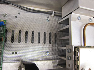
What
was the broadcaster to do? The answer was a two pronged approach. I verified
that the STL transmitters were in specification before adding RF shielding
inside the STL transmitter cabinets. In this case, most of the transmitters
were Marti STL-10, but two were of a newer vintage with internal rather than
external heat sinks. A photo shows the inside of one. I chose aluminum window
screen because the STL cabinet parts are aluminum and it could be purchased at a
local hardware store inexpensively. The best way to do this was to empty the
transmitter cabinet of the sub-assemblies and install the screen, holding it
down with existing hardware and some additional bolts through the cabinet. The
goal was to cover one inch long or longer ventilation holes that are one-eighth
wavelength or more at 1900 MHz. That took care of most of the cabinet
radiation.