 |
|
|
|
|
||||||||||
|
|
|
||||||||||
|
Technical
Tips from Mark W. Persons |
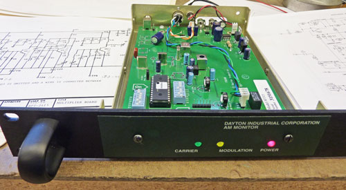
It is a very good choice for EAS monitoring, off-air monitoring, and now for AM/FM repeaters. However, Dayton Industrial is no longer in business so new ones are not available. |
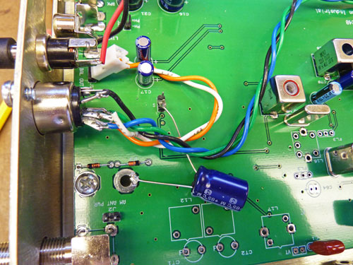
An additional problem was a peak in audio frequency response of about 6 dB at 180 Hz. The capacitor solved that problem too. |
| But wait, there is more to
the story! You could choose one of two IF (Intermediate
Frequency) filters when ordering a receiver, and one of two post-detection de-emphasis audio
filters by jumper option in the receiver. This chart gives measurement data on a typical
Dayton AF315 Receiver and compares it to the NRSC (National Radio Systems
Committee) recommendations that were later adopted by the FCC. The
plan is for audio to be pre-emphasized (high frequency boosted) when it
is broadcast and de-emphasized (high frequency attenuated) at the
receiving end to reduce noise when audio is heard. If the standard
is followed exactly, the result is flat frequency response. Most radios today have the audio high frequency response rolled off sharply after 3 or 4 KHz to reduce noise and listener complaints. They use narrow band IF components by design. Wide band IF receivers can only work well when the received signal strength is relatively high and when there is little nearby noise to interfere with the desired signal. Testing was done in January of 2011 while using the above mentioned 1000 mfd capacitor in the AGC circuit. |
|
Audio Frequency Response |
||||||||
|
Wide Band IF |
Narrow Band IF |
|||||||
|
Audio Frequency |
NRSC Standard |
50 us de-emphasis |
75 us de-emphasis |
50 us de-emphasis |
75
us de-emphasis |
Low frequency
response with AGC capacitor added |
||
| 30 Hz | 0 dB | -5.8 dB | -5.8 dB | -5.8 dB | -5.6 dB | -0.9 dB | ||
| 50 Hz | 0 dB | -2.5 dB | -2.6 dB | -2.6 dB | -2.5 dB | -0.1 dB | ||
| 100 Hz | 0 dB | 0.0 dB | 0.0 dB | 0.0 dB | 0.0 dB | 0 dB | ||
| 1 KHz | -0.75 dB | +0.9 dB | +0.4 dB | +1.3 dB | +1.2 dB | |||
| 2 KHz | -2.5 dB | -0.1 dB | -1.1 dB | 0.0 dB | -0.7 dB | |||
| 3 KHz | -4.3 dB | -0.1 dB | -3.0 dB | +2.3 dB | -3.8 dB | |||
| 4 KHz | -5.6 dB | -1.4 dB | -4.8 dB | -4.7 dB | -6.6 dB | |||
| 5 KHz | -6.9 dB | -4.1 dB | -6.4 dB | -17.2 dB | -19.3 dB | |||
| 6 KHz | -7.8 dB | -5.6 dB | -9.0 dB | -29.7 dB | -32.0 dB | |||
| 7 KHz | -8.6 dB | -7.1 dB | -9.6 dB | -40.7 dB | -41.8 dB | |||
| 8 KHz | -9.3 dB | -8.6 dB | -11.8 dB | -45.7 dB | -46.8 dB | |||
| 9 KHz | -9.7 dB | -11.2 dB | -14.2 dB | |||||
| 10 KHz | -10.0 dB | -14.6 dB | -17.3 dB | |||||
|
The stories go on and on.
Stop in again sometime. I'll leave the soldering iron on for you.
|
|
Questions? Email Mark Persons: teki@mwpersons.com |