 |
|
|
|
|
||||||||||
|
|
|
||||||||||
|
|
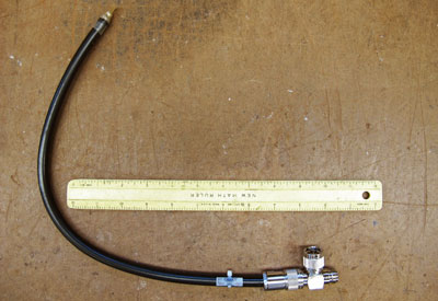
These are RF band-pass filters/shorted quarter wave shorted stub traps. They are a DC short that will pass an FM radio frequency with little or no attenuation. The left photo shows one with an N connector near a 12-inch ruler for size perspective. The one below is built with a BNC connector. Each one has a T connector so a normal FM transmission line can be interrupted for filter installation. |
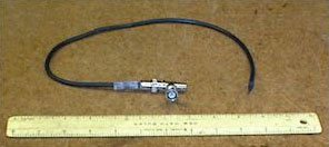 Shorted Quarter Wave Stub Trap with a BNC Connector
|
|
 |
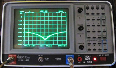 |
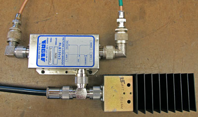
| Above
is the test setup required to calibrate the trap to the correct
frequency. A return loss bridge is used in conjunction with an RF
spectrum analyzer and 50-ohm dummy load. The analyzer display is a
VSWR picture of the performance of the trap at the frequency of
interest. |
|
| These filters are normally used at the output of
an FM (88 - 108 MHz) solid state broadcast exciter as a voltage spike protector.
It is, in essence, a shorted quarter wave stub made of 50 ohm transmission line.
They are needed on FM transmitters where the next stage of amplification is a
tube. An arc in that tube could send a spike of
hundreds or thousands of volts back to the exciter
causing failure of the exciter's output stage. Since the filter is DC shorted at the end, it presents a direct short to any DC voltages. It passes the FM frequency of interest because the cable is cut to an exact length. Each filter is cut and tested using a spectrum analyzer with tracking generator and return loss bridge. The return loss at the specified frequency is typically 45 dB, which a VSWR of 1.01:1. Sometimes they are used at the output of a low power FM station or an FM translator to give lightning protection to the final amplifier. They will also help reject second harmonic radiation as well as offer some attenuation to carriers that are not on the frequency they are cut for. FM BNC Stub Traps are rated at 250 watts. FM N Stub Traps are rated at
1000 watts. |
|
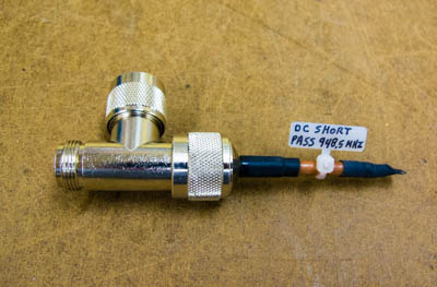 |
Here is one for the 944 to 952 MHz STL band.
It is typically used to protect transmitters and receivers from
static and lightning problems.
One attribute of this kind of stub is that it attenuates the second RF harmonic....IE: 1888 MHz to 1904 MHz. Power rated at up to 250 watts because of the cable size. |
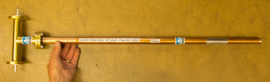 |
| Here is a stub trap made of
7/8"
rigid line with 7/8" EIA connectors. This one will help protect a
2 KW FM transmitter from lightning problems.
|
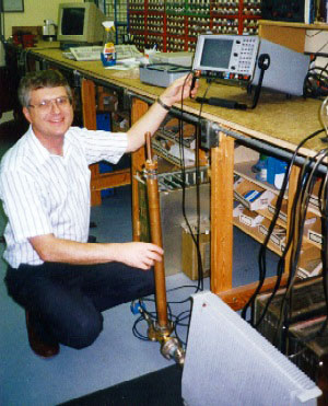 |
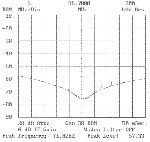
Here is Mark Persons in his shop
demonstrating that a shorted quarter wave stub makes a
good second harmonic trap
for an FM broadcast transmitter. Attenuation
at twice the station's assigned frequency
exceeds 30 DB.
The trap is a 1-5/8" coaxial cable T with an adjustable quarter wave shorted section attached. Input to the T is the station's transmitter. The T output goes to the transmission line leading to the broadcast antenna. A dummy load, to the right of the T, is shown in this photo. It was used for testing purposes. On the bench is an IFR A-7550 Spectrum Analyzer with tracking generator. The IFR A7550 works from 9 KHz to 1 GHz. It is excellent for looking at RF emissions and RF circuits. Analysis is done in minutes rather than hours by previous methods. |
|
 |
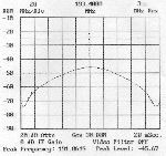 |
The left plot is a return loss measurement of the filter. The operating frequency of the radio station is in the middle where the match is the best. The right plot shows return loss at both the station's frequency and at the second harmonic. The filter absorbs second harmonic transmitter output while passing the station's main signal without attenuation. |
|
The stories go on and on.
Stop in again sometime. I'll leave the soldering iron on for you.
|
|
Questions? Email Mark Persons: teki@mwpersons.com |