|
What do you do when a
high-voltage blocking
capacitor in an FM
transmitter fails?
We are talking about the
large cylinder that
surrounds a tube. It is
actually one aluminum
cylinder within another,
with insulating (dielectric)
material in between. The
purpose is to transfer RF
energy from the tube anode
to the output-tuning network
without shorting
high-voltage DC to ground.
That direct current often is
connected directly to the
tube via a clip on the
anode.
So there you are with a
shorted blocking capacitor
and no replacement on the
shelf. (Why would the
station have a spare when
they fail only once in 20
years or so?)
My story goes back to a cold
day in January, when it took
a farm snowplow to clear a
road to a transmitter site
(Fig. 1). Such is life in
Minnesota during the winter.
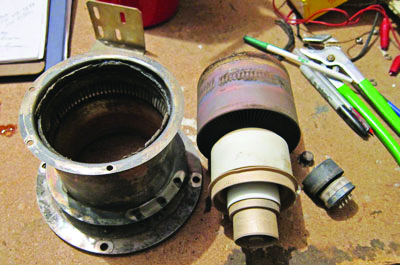
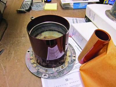
Fig. 2 shows the charred
remains of a PA tube, a
driver tube and a
high-voltage blocking
capacitor from a CCA FM2500B
FM Transmitter. The normal
tube appearance is of
nickel-plating, not
brown-red. The blower motor
quit, but the transmitter
kept running when the
airflow switch stayed in the
on position. The switch
worked normally when tested
a year before, so I can only
assume it stuck from being
on for a long time.
 |
 |
| Fig. 2:
These items have
overheated. |
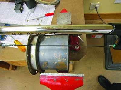
Fig. 3:
Hacksaw the outer
cylinder. |
NO SPARES
This transmitter normally
runs 2,200 watts using a
3CX400A driver tube and
3CX3000A7 PA tube. The
client keeps spare tubes on
the shelf so that was not a
problem, but who keeps an
extra blocking capacitor?
Since there was no spare,
the only option to avoid two
days of off-air time was to
rebuild the original
capacitor. This particular
type of capacitor was not
designed for rebuilding, but
what else was there to do?
It�s not rocket science!
I took the capacitor to the
shop and used a hacksaw to
cut through the outer
cylinder and just into the
dielectric between the outer
and inner cylinders.
 |
 |
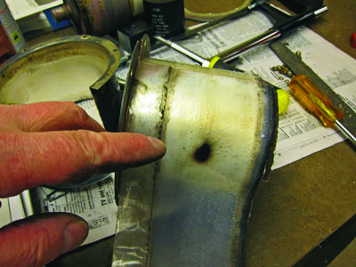
| Fig. 4:
Note the arc-over
spot. |
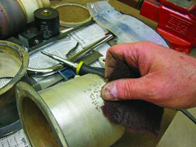
Fig. 5:
Clean to smooth
rough edges. |
After unwrapping and
exposing the original
dielectric, I found an
arc-over spot. Now the real
work began.
Plenty of cleaning was
needed to get sharp edges
and other blemishes down to
prevent future arc-overs. A
file and 3M Scotch-Brite
scouring pads worked well
here. I remember hearing of
someone who replaced
dielectric material without
removing the sharp edges,
only to have the same arc
problem immediately again!
I found new Kapton
dielectric material on the
shelf at a nearby station
and wound it onto the inside
cylinder of the blocking
capacitor; then the outer
cylinder was put back on.
This thin Kapton sheet is
4-3/4 inches wide and is
used by Continental
Electronics in its
transmitter blocking
capacitors. At less than $90
from Continental, it is
worth keeping some on the
shelf. A complete blocking
capacitor, which includes
the two metal cylinders,
costs $450 to $1,500
depending on which
transmitter and manufacturer
you order one from. Kapton
has a reddish-brown color,
as opposed to the original
clear-white, which was
probably Teflon, in this
case.
 |
 |
| Fig. 6:
Use some of the
Kapton material you
keep on the shelf. |
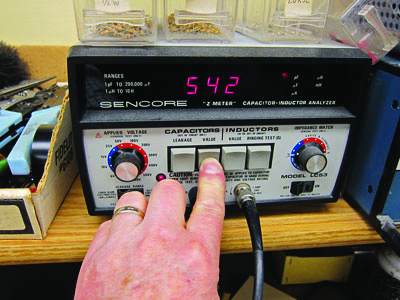
Fig. 7:
Measure capacitance
to confirm it is
right. |
The original capacitor
had six turns of dielectric
sheet, but capacitance
testing, using a Sencore Z
Meter, showed that was one
turn too many with this new
material.
TESTING
The proof is in the
capacitance of the assembly.
Here the rebuilt blocking
capacitor measures very
close to the original 550
pf. Yes, I was able to
determine the capacitance of
the original shorted
capacitor because testing
was with just a few volts,
rather than the normal 4,000
volts in the transmitter.
Two stainless
steel hose clamps were used
to hold the outer cylinder
tight on the dielectric.
Stainless is not
ferromagnetic. I pointed
this out in a December 2013
article in Radio World (Fix
a Transmitter Tube Socket,
radioworld.com,
keyword Socket). This is
important as anything that
is attracted by a magnet in
a high RF field will tend to
vibrate at the RF frequency
and sometimes melt. Use an
ordinary small magnet to
verify that nothing in the
RF area is attracted
magnetically.
 |
 |
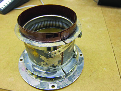
| Fig. 8:
Here's the
reassembled blocking
capacitor. |
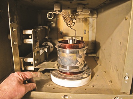
and
the blocker is back
in the transmitter. |
Fig. 9 shows the final
assembly, back in the
transmitter, just before
high voltage was turned on.
Yes, the outer parts of the
blocking capacitor have an
oxidized appearance. They
are silver-plated and get to
look that way from years of
exposure to air. The
oxidation does not hurt
transmitter performance.
Success � no arcs and the
operating parameters came
back to normal.
This is a permanent fix for
the problem and the blocking
capacitor is more repairable
if this should happen again
in the future. It makes
perfect sense.
Mark Persons, W0MH, CPBE, has over 30 years
experience. He has written
numerous articles for
industry publications over
the years. His website is
www.mwpersons.com. |