 |
|
|
|
|
||||||||||
|
|
|
||||||||||
|
Technical Tips from Mark W. Persons |
|
For Harris FM-25K and FM-35K FM Broadcast Transmitters |
|
|
This is a Harris FM-25K FM Broadcast Transmitter from the mid 1980's. It is very similar to the FM-35K. Both have an external power supply cabinet. |
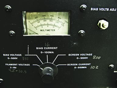 |
If you encounter a situation where the transmitter is off the air and the filament voltage meter is reading negative, then you have NO filament voltage, not a negative voltage. |
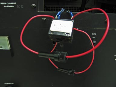 |
The problem is
sometimes traced to a bad circuit breaker on the front panel. A
good TEMPORARY fix is to solder inline fuses across the breaker.
This will get the transmitter running while a replacement breaker is
ordered and on the way. To prevent circuit breaker failure from poor contacts, it is recommended that the breaker by cycled regularly. Doing this is easy if you get in the habit of turning off all of the transmitter circuit breakers after you shut off the 208 or 240 VAC incoming power for regular maintenance. Then, turn the breakers on again after the power is restored. This will exercise the breaker contacts.
|
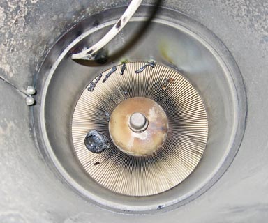 |
If you hear a loud
BANG when you turn the transmitter on, it may be that the high voltage
has shorted to ground above the PA tube. You can look through
vents on the top of the transmitter to confirm this. Assuming this
is the problem, you will need to remove the back of the PA cavity at the
rear of the transmitter. There are at least 20 screws holding it
on.
In this particular case, the plate cap came loose and burned up along with burning off the end of the high voltage (9000 Volt) lead to the tube anode. A bit of a mess. |
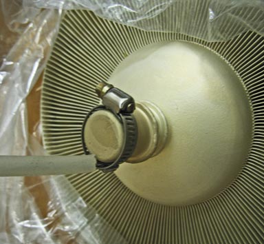 |
If you do not have a replacement tube cap, you can use a stainless steel hose clamp to hold the high voltage wire to the tube anode. This photo shows the spare Econco rebuilt tube that was still in the box with a plastic bag around it to illustrate how to connect the lead. In this case, the transmitter high voltage lead was too short so a TEMPORARY lead was fashioned by using the center conductor and dielectric from a piece of RG-214/U coaxial cable. Note the lead is hooked around the far end of the hose clamp so it is less likely to come off again. |
|
The stories go on and on.
Stop in again sometime. I'll leave the soldering iron on for you.
|
|
Questions? Email Mark Persons: teki@mwpersons.com |